
RDS Information for USA
Data gathered from http://www.telecomponents.com/catalog/pdf/Radio%20data%20system%20Initel.pdf on the Internet Archive (on site backup).
Other information obtained from Wikipedia and NRSC's 1998 RBDS standard documentation, content rights were met or exceeded.
» If you have any news, updates, additions or corrections... e-mail them to [email protected].
What is RDS?
RDS or Radio Data System is standard on most car radios and hi-fi tuners today. RDS is used on VHF FM radio broadcast transmissions and provides a number of facilities that are of great use to all radio listeners, but particularly to those radio listeners in cars. RDS enables traffic reports to be received more easily, and provides many facilities including enabling the radio station name to be displayed on the radio display.
The system has gained a considerable amount of popularity and is widely used in Europe where it has been established for a number of years.
RDS, Radio Data System Development
The Radio Data System development took place mainly in Europe where it was first launched and deployed.
The first developments took place in Germany where system was developed to place traffic information onto FM broadcasts using a 57 kHz subcarrier.
This trial development was taken up by the European Broadcasting Union, EBU when in 1974 their technical committee proposed a development of the German project to carry traffic information as well as other data. It would also allow automatic re-tuning of a receiver when it went outside the range of one transmitter, and it would provide facilities such as programme information, etc.
Using experience from the original scheme as well as a modulation format from a Swedish paging system and baseband coding developed by the British Broadcasting Corporation, BBC and the Irish radio, IRT, the first RDS specification was launched in 1984.
The standard was subsequently enhanced in 1991 with features including alternative frequencies functionality and it was published under the auspices of the European Committee for Electrotechnical Standardization, CENELEC.
In North America the idea was taken up and the US National Radio Systems Committee issued their version known as the Radio Broadcast Data System, RBDS in 1992.
The CENELEC standard was updated in 1992 with the addition of Traffic Message Channel and in 1998 with Open Data Applications and, in 2000, RDS was published worldwide as IEC standard 62106.
RDS Facilities
The RDS system offers a wide range of very useful facilities. The most widely publicised one is that of being able to provide travel news. This is available on most local radio stations. All of these stations transmit the TP code to identify that travel messages are flagged by RDS. When the radio is set for travel news it will only tune to stations which carry the TP indication. As the station is about to broadcast a travel announcement the TA code is transmitted. If a CD or cassette is being played then most sets will actually pause the CD or tape and then allow the travel announcement to be heard. In addition to this the volume may also be set slightly higher to allow the announcement to be heard more easily.
Autotuning
RDS brings intelligence into the tuning of a radio. The autotuning facility comes into its own on long journeys when the car moves from the service area of one transmitter to the next. Without RDS the radio has to be manually tuned to the next station. This is not always easy because it is difficult to reliably detect which is the strongest station.
An RDS set will look for the Programme Identification or PI code. A national network will be broadcast from a large number of different transmitters around the country. The station or network eg Radio 4 will have its own PI code. When the radio moves out of the range of one transmitter the radio will seek the strongest signal which has the same PI code, allowing the radio to remain tuned to the same programme.
When radios fitted with RDS store a station frequency, they also store the PI code along side it. This has the advantage that when the radio is turned on in a place outside the coverage area for the transmitter frequency which is stored then the radio will seek the strongest signal which has the correct PI code.
Local radio stations also have a PI code. In view of the local nature of these stations the PI code works slightly differently.
If the station has two or more transmitters then the PI code will operate in the normal way when it is range of these transmitters. However when the radio moves outside this coverage area it will retune to the strongest signal of the same type of station.
The PI code consists of four characters. The first indicates the country of origin and for the UK this is C. The next one indicates the type of coverage. The figure "2" indicates a national station, and the final two characters are the programme reference. For example Radio 3 has the PI code C203 and BBC GLR has C311.
RDS Instant Tuning
It takes a number of seconds for the radio to search for the strongest signal with the correct PI code. During this time the radio would mute itself and the listener would have an annoying gap in listening. To enable the set to tune itself very quickly from one transmission to the next each transmitter broadcasts a short list of frequencies of adjacent transmitters. This vastly reduces the amount of seeking which the radio set has to perform. In addition to this a second front end is often employed to constantly detect the strength of the alternative frequency transmissions. This results in much faster changes in setting - to the extent that the listener should not be able to detect when the radio changes from one transmitter to another.
Another facility associated with tuning is called the Programme Service Name (PS). This enables the set to display the station name. This normally takes a second or two to come up on the display after the station has been tuned in. However it is a most useful facility with the ever-increasing number of stations on the air
Additional RDS Facilities
A new feature which has been added to RDS is called Enhanced Other Networks (EON). This allows the set to listen to one station like a national network, but still be interrupted by travel news from a local radio station. This feature even allows announcements to be heard whilst travelling in silence or listening to a tape.
EON requires a large amount of co-ordination between the different stations. To achieve this, the BBC have a central computer specifically for this purpose. When a local radio station is about to transmit a traffic message the fact is flagged to the computer. In turn this directs the relevant national radio transmitters to indicate this fact, thereby enabling the radios to change frequency to the local radio station to receive the message. Once the message is complete the radio will return to its original station.
EON is relatively new and the first sets to have it included only appeared in 1991. Although it is being introduced on more sets, the majority still does not have it. However with manufacturers constantly bringing new sets onto the market EON should be included on far more sets in a year or two.
FM RDS technology uses the basic radio broadcast FM signal and introduces new elements to the signal to carry the RDS data. By adding additional elements to the signal that do not interfere with the normal mono or stereo operation, non-RDS receivers are able to operate when the RDS technology is present on the signal.
How RDS Works
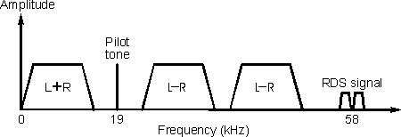
RDS operates by adding data to the baseband signal that is used to modulate the radio frequency carrier. The baseband signal consists of a number of components. Firstly there is the mono audio consisting of the left plus right (L+R) component that is transmitted at the normal audio frequencies up to 15 kHz.
The stereo difference signal is then amplitude modulated as a double sideband suppressed carrier signal at 38 kHz. A pilot tone at 19 kHz (half the frequency of the stereo difference signal subcarrier) is also transmitted and this is used to enable the receiver demodulator to exactly recreate the 38 kHz subcarrier to decode the stereo difference signal. The stereo difference signal is above the audio hearing range and as a result it does not detract from the normal mono signal. When adding anything new to a transmission, compatibility must be maintained with existing radios.
The RDS information is placed above the stereo difference signal on a 57 kHz subcarrier as shown. This happens to be three times the stereo pilot tone frequency. For stereo transmissions the RDS subcarrier is locked onto the pilot tone. It can either be in-phase with the third harmonic of the tone, or as in the case of the BBC it can be in quadrature.
The actual subcarrier that is used to carry the information is phase modulated to carry the data. It uses a form of modulation called Quadrature Phase Shift Keying (QPSK). This gives good immunity to data errors caused by noise whilst still allowing the data to be transmitted at a suitable rate. Combined with the fact that the subcarrier operates at a harmonic of the pilot tone, these facts minimise the possibility of interference to the audio signals.
RDS Baseband Coding
The rate at which data is transmitted is 1187.5 bits per second. This is equal to the frequency of the RDS subcarrier divided by 48. By adopting this data rate the decoding circuits to operate synchronously. This reduces problems with spurious signals in the decoding circuits.
Data is transmitted in groups consisting of four blocks. Each block contains a 16 bit information word and a 10 bit check word as shown. This means that with the data rate of 1187.5 bit per second approximately 11.4 groups can be transmitted each second.
A 10 bit check word may seem to be long. However it is very important in view of the poor signal conditions which can exist. This can be particularly true for car or portable radios. The check word enables the radio decoder to detect and correct errors. It also provides a method for synchronisation.
The data groups are structured so that data can be transmitted as efficiently as possible. Different stations will want to transmit different types of data at different times. To cater for this there are a there are a total of 16 different group structures. Their applications are outlined in Figure 3.
Mixing of different types of data within groups is kept to a minimum. However the coding structure is such that messages which need repeating most frequently normally occupy the same position within groups. For example the first block in a group always contains the PI code and PTY and TP are to be found in block 2.

In order that a radio knows how to decode the data correctly, each type of group has to be identified. This function is performed by a four bit code occupying the first four bits in the second block.
Once generated the data is coded onto the subcarrier in a differential format. This allows the data to be decoded correctly whether the signal is inverted or not. When the input data level is "0" the output remains unchanged but when a "1" appears at the input the output changes its state.
With the basic signal generated the spectrum has to be carefully limited. This has to be done to avoid any cross talk in phase locked loop decoders. The power density close to 57 kHz is limited by the encoding each bit as a bi-phase signal. In addition to this the coded data is passed through a low pass filter.
RDS PTY Codes & Programme Types
One of the key elements of RDS is that it is possible to identify the type of station.
Each RDS transmission carries and RDS PTY code, and this indicates the "Programme TYpe".
The RDS PTY code has a given value and this indicates the type of programme material carried.
The RDS PTY codes have slightly different categorisations dependent upon whether the stations are in Europe or North America. For Europe the RDS Forum developed the standards, whereas within North America the system is known as the RBDS, Radio Broadcast Data System. When the RBDS standard was developed, no attempt was made to match the original RDS plan for PTY type numbers.
| RDS PTY Code | Europe | North America |
|---|---|---|
| 0 | No programme type defined | No programme type defined |
| 1 | News | News |
| 2 | Current affairs | Information |
| 3 | Information | Sport |
| 4 | Sport | Talk |
| 5 | Education | Rock |
| 6 | Drama | Classic Rock |
| 7 | Culture | Adult Hits |
| 8 | Science | Soft Rock |
| 9 | Varied | Top 40 |
| 10 | Popular Music (Pop) | Country Music |
| 11 | Rock Music | Oldies (Music) |
| 12 | Easy Listening | Soft Music |
| 13 | Light Classical | Nostalgia |
| 14 | Serious Classical | Jazz |
| 15 | Other Music | Classical |
| 16 | Weather | Rhythm & Blues |
| 17 | Finance | Soft Rhythm & Blues |
| 18 | Children's Programmes | Language |
| 19 | Social Affairs | Religious Music |
| 20 | Religion | Religious Talk |
| 21 | Phone-in | Personality |
| 22 | Travel | Public |
| 23 | Leisure | College |
| 24 | Jazz Music | Not assigned |
| 25 | Country Music | Not assigned |
| 26 | National Music | Not assigned |
| 27 | Oldies Music | Not assigned |
| 28 | Folk Music | Not assigned |
| 29 | Documentary | Weather |
| 30 | Alarm Test | Emergency Test |
| 31 | Alarm | Emergency |
RDS Radio Data System Acronyms and Abbreviations
RDS has been successfully in use for many years,. However there are many RDS acronyms or abbreviations that are used with RDS.
The RDS acronyms can be confusing as they are not always mentioned in the literature associated with a particular radio, or the instruction manual may be lost.
The common RDS acronyms and abbreviations relate to the various operational modes and facilities. These RDS acronyms are widely used in view of the fact that within countries that have adopted the system, most car radios today incorporate RDS as standard.
| RDS Code | Meaning | Description |
|---|---|---|
| AF | Alternative Frequencies | A list of a station's frequencies in adjacent transmitter areas. |
| CT | Clock Time and Date | Data containing time and date information so that the receiver can display. Using this signal has the advantage over a self-contained clock in the radio that it adjusts itself to changes between BST and GMT (UTC) and it does not loose or gain time. |
| DI | Decoder Information | This signal allows for miscellaneous function in the radio to be controlled |
| EON | Enhanced Other Networks | Information transmitted giving the radio a cross-reference to other stations for Travel service and other features. |
| MS | Music/Speech | This allows for the relative levels of speech and music to be altered. |
| PI | Programme Identification | This is a station code used in conjunction with AF data to provide automatic tuning to the best signal for a chosen service. |
| PIN | Programme Identification Number | This signal identifies a given programme and allows the radio to turn itself (and possibly a recorder) on for that programme. |
| PTY | Programme Type Selection | A signal which allows for the selection of listening by one of 15 types of programme rather than by the station. |
| PS | Programme Service Name | A signal which enables the name of the station to be displayed. |
| RT | Radio Text | This allows information about the programme to be displayed by the radio. |
| TDC | Transparent Data Channel | This allows for data to downloaded via RDS. |
| TP/TA | Travel Service | These signals enable the travel information to be heard, regardless of the choice of listening. |
RDS Logos


Note: The wording "RADIO DATA SYSTEM" may be omitted.
When EON is implemented, the following logos may be used:

